Nmos Inverter Circuit Diagram
Scaling of cmos circuits.

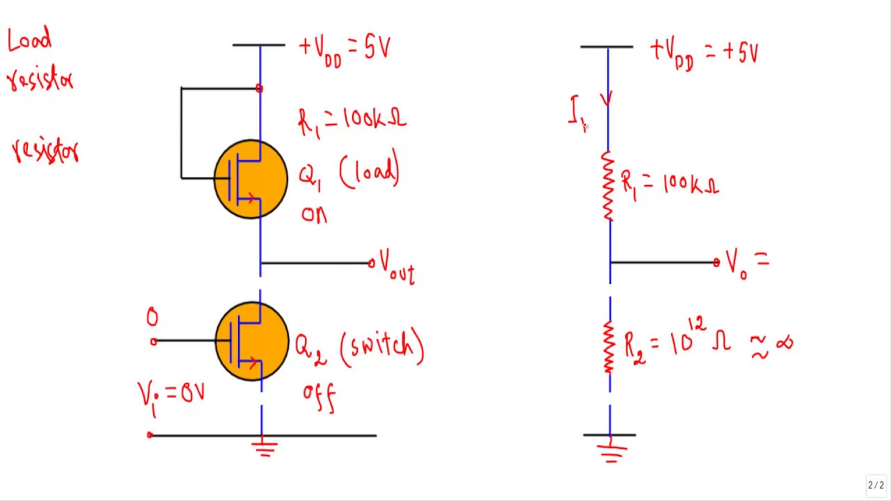
Nmos inverter circuit diagram. Nmos inverter chapter 16 nmos logic circuit chapter 162. 15 nmos logic circuits are constructed by connecting driver transistor in parallel series or series parallel combinations to produce required output logic function nmos logic circuit logic gates in 0 1 out and gate or gate in 0 1 out in 0 xor gate 1 out in out not gate logic gates nmos nor gate nmos nor gate can be constructed by. Pmos circuit diagram transistors pmos and nmos in cut off electrical engineering pmos characteristics circuit diagram pmos circuit diagram pmos inverter circuit diagram pmos schematic diagram. Static nmos inverter transistor t 1 acts as an inverter t2 acts as active load replacing the static resistor mos technology use transistors as playing resistor role.
Lecture 20 today we will look at why our nmos and pmos inverters might not be the best inverter designs introduce the cmos inverter analyze how the cmos inverter works. In this video i have described how to draw a stick diagram of n mos and p mos. 6012 microelectronic devices and circuits fall 2005 lecture 13 14 nmos inverter with current source pull up allows fast switching with high noise margins. Figure 51 shows the circuit diagram of a static cmos inverter.
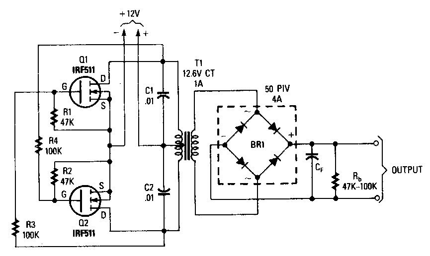
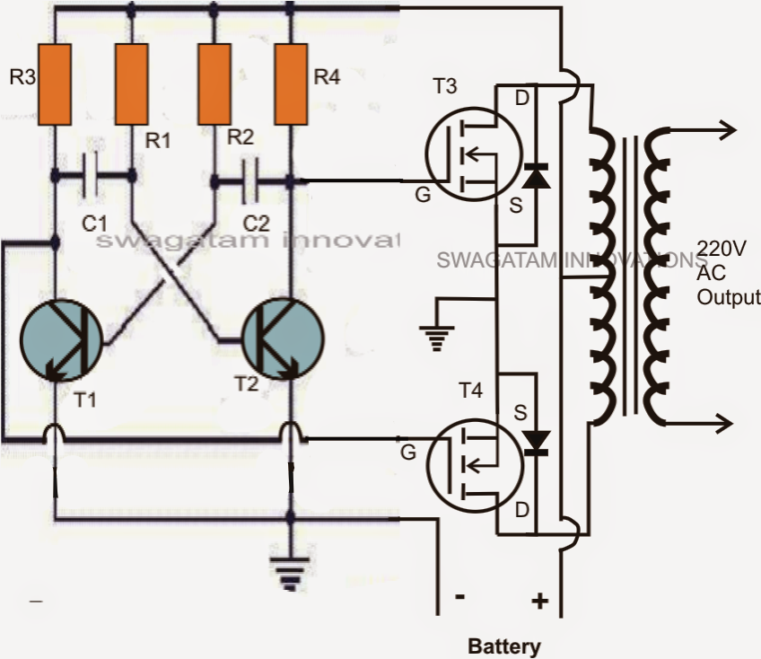
Its operation is readily its operation is readily understood with the aid of the simple switch model of the mos transistor introduced in. An inverter circuit outputs a voltage representing the opposite logic level to its input. Its main function is to invert the input signal applied. Simple low power inverter circuit 12v dc to 230v or 110v ac diagram using cd4047 and irfz44 power mosfet gallery of electronic circuits and projects providing lot of diy circuit diagrams robotics microcontroller projects electronic development tools.
Inverter stick diagrams nand gate stick diagrams nor gate stick diagram. Layout design rules 6.
Circuit Structure Of Pseudo Nmos Inverter Download Scientific Diagram

Vlsi Design Mos Inverter

Vlsi Design Mos Inverter

Simple 12v To 230vac Inverter Circuit Mosfet Diy Electronics
Nmos Inverter Youtube

Vlsi Design Mos Inverter
Best Power Mosfet Inverter Circuit Diagram World Of Technology

500 Watt Inverter Circuit Diagram Using Mosfet Grow Amis

Nmos Inverter Circuit Download Scientific Diagram

Vlsi Design Mos Inverter

Simple 100w Inverter Circuit Working And Circuit Diagram Updated

Sspd Chapter 7 Part 5 Stick Diagrams Of Logic Gates Continued 2

Cmos Inverters

Depletion Load Nmos Inverter

Wiring Panel Power Mosfet Inverter Circuit Diagram

Mosfet Why Does There Have To Be A Load In Mos Inverters

5 4 Nmos And Pmos Logic Gates Introduction To Digital Systems

1000 Watt Power Inverter Circuit Diagram Circuitstune

The Mos Transistor

Mosfet Power Inverter 500w Using Rfp50n06 Inverter Circuit And

Depletion Mosfet Inverter Electrical Engineering Stack Exchange
Wiring Machine Mosfet Inverter Circuit Board

Why Is A Pmos Connected To A Vdd And Nmos Connected To The Ground

Vlsi Design Mos Inverter

Nmos Inverter And Its Characteristics Youtube

What Is The Difference Between Nmos And Cmos Technology

Cmos Based Inverter Circuit Operation Explained Youtube

Ee 2212 Experiment 5 23 October And 6 November Mosfet I V

Mosfet Circuits Electrical4u

Power Inverter Circuit Switch Mode In 2019 Electronic Circuit

Solved Question 4 Consider The Following Pseudo Nmos Inve

The Following Post Shows How A Full Bridge 1 Kva Inverter Circuit

Suraj Kamya Cad Lab Exp 03

Circuit Structure Of Pseudo Nmos Inverter Download Scientific Diagram

Ic 4093 With Mosfet Inverter Circuit Inverter In 2019 Simple

500w Dc To Ac Inverter With Fet Irfp260 Inverter Circuit And Products

Make This 1kva 1000 Watts Pure Sine Wave Inverter Circuit

Nmos Inverter

1000w Power Inverter Circuit Diagram This Is The Power Inverter

500w Power Inverter Circuit Using Sg3526 Irfp540

How To Make 12v Dc To 220v Ac Converter Inverter Circuit Design

Solved An Nmos Inverter With Saturated Load Is Shown In Figure

1000w Inverter Circuit And Kit Electronics Solution Hifi

500w Power Inverter Circuit Using Sg3526 Irfp540

Can I Have A Practical Inverter Circuit Quora

A Optical Image Of A Fabricated Sno 2 Gated Nmos Inverter B

Explain The Principle Of Operation Of Mos Inverter

How To Make An Inverter Simple 40 Watts Inverter Circuit

Ece 2212 Experiment 5 13 March 27 March 3 April 2014 Mosfet

12v To 230v Inverter Circuit Schematic Using Pulse Width Modulator
